


Description
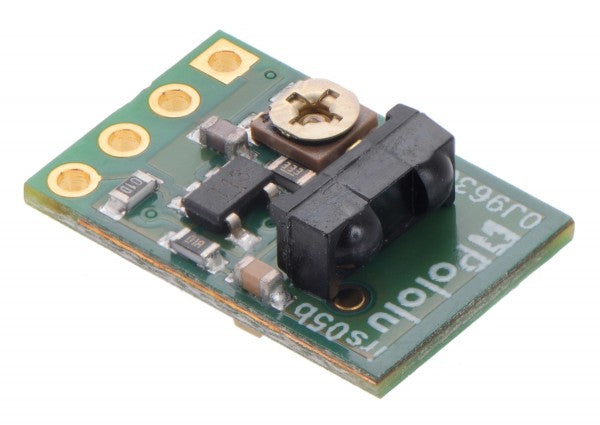
This module features a 38 kHz modulated IR sensor with fixed gain and an IR LED with oscillator circuit, making the module a tiny proximity sensor. This low-brightness version draws an average of 16 mA at 5 V and has a sensor range of about 60 cm. A low-brightness version with a sensor range of 30 cm is also available.
The sensor module is based on a modulated Vishay TSSP77038 infrared receiver. Unlike most IR receiver modules designed for remote control of devices (e.g. TVs), the TSSP77038 has a fixed gain (sensitivity). This lets the sensor work better when used as a proximity or reflectance sensor.
The module combines the TSSP77038 and a 555-timer-based LED circuit and requires only 3.3 V to 5 V.
The enable input can be used to control whether the IR LED is on, and the digital output indicates whether an object has been detected.
Sensor connections
The proximity sensor has four connections: ground (GND), the logic power supply (VDD), digital detection indicator (OUT) and IR emitter enable (ENABLE).
The logic power, VDD, should be between 3.3 V and 5 V. A supply of less than 5 V will reduce the IR LED brightness and the range. To run the sensor at full brightness at 3.3 V, the jumper on the emitter side of the board should be bridged.
The OUT pin, which is high by default, stays low as long as the TSSP77038 receiver detects a sufficient signal. At the edge of the detection range, the output switches between high and low. A red LED on the emitter side of the board is activated when the sensor detects something.
The ENABLE pin turns off the IR emitter LED when it is driven low. The pin is pulled high by default and can be left disconnected if dynamic control of the IR emitter is not needed. A green LED on the emitter side of the board is connected in parallel with the IR LED, which lets you see whether the IR LED is active.
The four connections are arranged with 0.1" spacing along the edge of the board, making it compatible with solderless breadboards or other 0.1" grids.
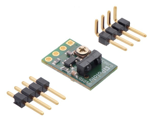
You can solder wires directly to the board or use the 4x1 straight male header or the 4x1 right-angle male header included in the package.
Adjusting the emitter frequency
The trimmer potentiometer on the receiver side of the sensor can be used to adjust the frequency of the IR transmitting LED.
The detection range can be maximized by tuning to 38 kHz, or it can be used deliberately to shorten the detection range.
Limitations
- This sensor will only indicate that an object is within its range, not how far away it is. At the edge of the detection range, the output switches between high and low (see left oscilloscope image below).
- The sensor only detects whether it receives a signal back from an object. Object size and reflectivity (in the IR range) therefore affect detection.
- The detection angle is relatively wide in both directions. The high-brightness version in particular may require additional consideration during mounting to prevent surfaces parallel to the sensor's line of sight from becoming visible. For many applications, additional shielding can be used to block unwanted detection paths, such as reflections from the ground, or to reduce interference from ambient lighting. When applying shielding, note that reflections from the shielding itself can cause unwanted activation of the sensor.
- This sensor can be triggered by ambient IR (e.g. from fluorescent tubes - see right oscilloscope image below). Analyzing the correlation between the output and toggling of the enable input can also be used to mitigate ambient interference.
- Multiple sensors can interfere with each other.
 |  |


Another approach is to use a multimeter to measure the current draw of the sensor. The low-brightness version draws about 8 mA at 5 V, while the high-brightness version draws about 16 mA at 5 V.
Encrypted payment
Your payment information is processed securely. We do not store credit card details nor have access to your credit card information.
Customs tariff number:
Country of origin:
This depends on where you are located. Once the order has been handed over to UPS, the delivery time in Germany is approx. 2-3 days, within Europe approx. 1 week.
We dispatch our articles with our shipping partner UPS.
If we have not yet answered your question, you can contact us and we will get back to you as soon as possible.