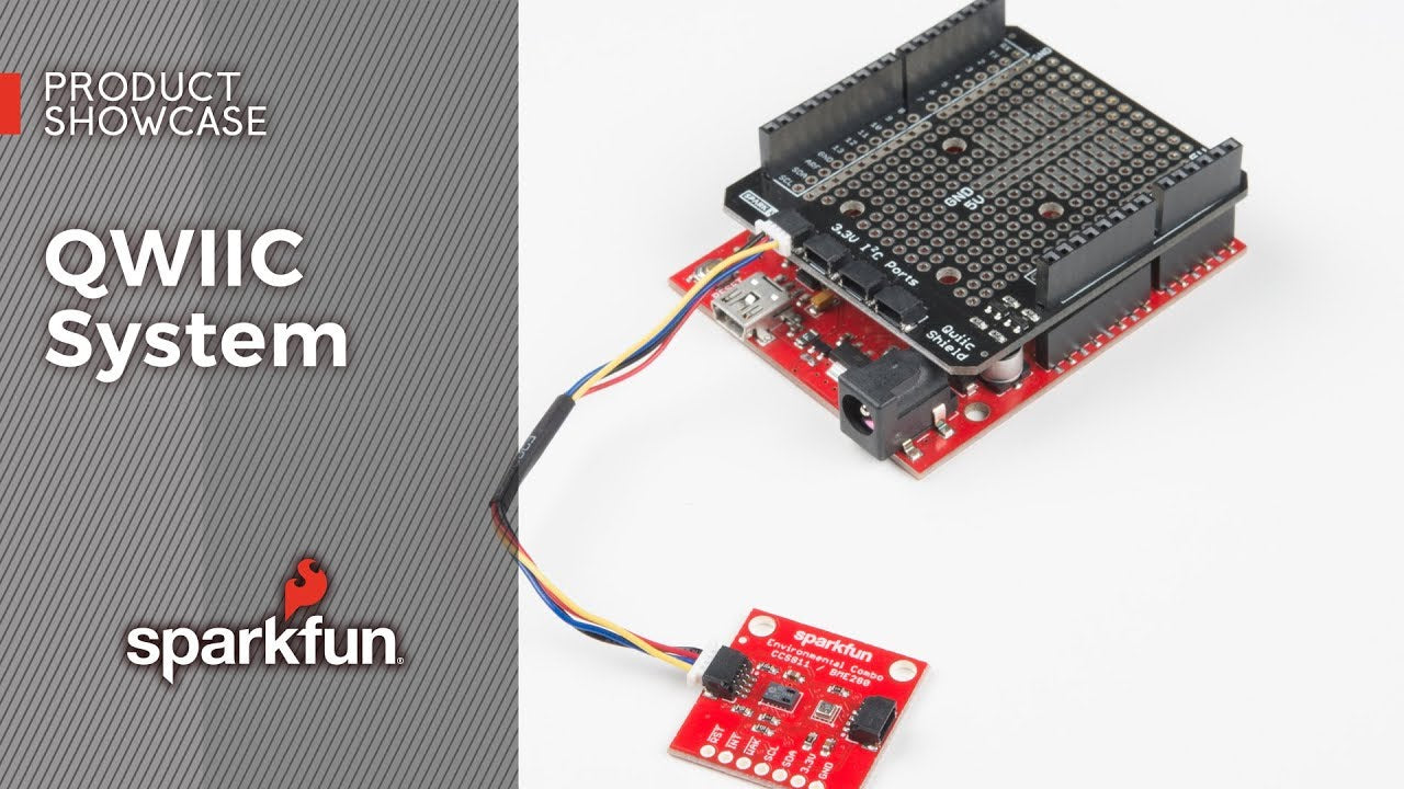
Das Sparkfun QWIIC System


The QWIIC Connect system was developed to make prototyping easier for you.
The QWIIC Connect System uses the Inter-Integrated Circuit Protocol. The I2C protocol allows multiple digitally integrated circuits ("slave" chips) to communicate with one or more "master" chips using only two wires.
This technology offers the following advantages within the QWIIC ecosystem:

The cables can be easily plugged in between the boards, which makes quick work of setting up a new prototype easier. Sparkfun currently offer three different lengths of QWIIC cables as well as a breadboard-friendly cable. Initially, you may need to solder headers onto the shield to connect your platform to the QWIIC system, but once that's done, it's plug-and-go!
How many times have you swapped the SDA and SCL cables on your breadboard in the hope that the sensor will work? The QWIIC connector is polarised, so you always wire your project correctly from the start.
The PCB connector is an SM04B-SRSS. The mating connector is a SHR04V-S-B. These are common and inexpensive connectors.
Use the I2C buses. Most QWIIC boards have two or more connectors that can be used to connect multiple devices.

Any microcontroller with I2C can work with the QWIIC ecosystem. We currently have the corresponding shield or HAT in our programme for working with Arduino and Raspberry Pi.
Sparkfun also offers RedBoard Turbo as a mainboard with QWIIC connection.