What is a breadboard?
Breadboards are indispensable tools when learning electronics or prototyping new designs, and are thus frequently used in the Arduino environment. But what exactly are they?
A breadboard or solderless breadboard is great for making temporary circuits and prototypes. Since no soldering is required to create a circuit, they are perfect for temporary designs or for quickly testing ideas. They can also be used over and over again.
Components are pushed into the sockets on the breadboard and then additional jumper wires are used to make connections.
Building a breadboard
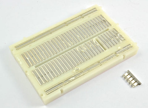
If you were to peel the self-adhesive backing off the back of your breadboard, it would look something like this.

The middle part of the board is two columns of 30 connecting strips each, like the one pulled out and on the side of the breadboard. These connect everything that is put through from the front into one of these five holes.
On both edges of the board are much longer clip sections that connect the columns of holes marked by the blue and red lines on the front of the pegboard. These are usually used for GND (blue) and 5V (red).

HORIZONTAL ROWS - TERMINAL STRIPS
On the picture with the glue removed, you can see many horizontal rows of metal strips on the bottom of the breadboard.
The tops of the metal rows have small clips hidden under the plastic holes.

These clips allow you to insert a wire or the leg of a component into the exposed holes of a pegboard and hold it there.

Once inserted, this component will be electrically connected to all other elements in this row. This is because the metal rows are conductive and allow current to flow from any point in that strip.
Note that there are only five clips on this strip. This is typical of almost all breadboards. Thus, you can only connect up to five components in a given section of the pegboard. Although the row has ten holes, each horizontal row is separated by a column (CENTERLINE) on the pegboard. This column isolates both sides of a given row from each other and they are not electrically connected.

POWER BUS - BUSBARS
In addition to horizontal rows, breadboards usually have so-called power buses that run vertically along the sides.

These power rails are metal strips identical to those that run horizontally, except that they are usually all connected together. When you build a circuit, you usually need power in many different places. Power rails give you easy access to power anywhere in your circuit. Usually they are marked with a "+" and a "-" and have a red and blue or black stripe to indicate the positive and negative sides.
It is important to know that the power rails on both sides are not connected. So if you want the same power source on both sides, you will need to connect the two sides with some jumper cables. Note that the markings are for reference only. There is no rule that says you must connect power to the + rail and ground to the - rail, although it is good practice to keep everything in order.


