Before we define a potentiometer, let's take a quick look at what a resistor is. A resistor is a basic electrical element with two terminals that resists the flow of electrical current when a voltage is applied between the two terminals. The value of the resistor determines how much current will flow as a function of the voltage applied across the terminals, and is given by Ohm's law as I = V / R.
Imagine there is a way to add a third terminal to the resistor that can be moved around. By adding a movable third terminal, the resistor is converted into a potentiometer. Therefore, a potentiometer can be defined as a three-terminal resistor with a variable or movable contact that divides a voltage into two parts.
Two types of potentiometers
A distinction can be made between linear and rotary potentiometers.
The difference between the two lies in the mechanical construction of the potentiometer. A potentiometer consists of four main components: two fixed terminals, a movable terminal (called a wiper), a resistor strip or track, and the case.
For both the linear and rotary potentiometers, the third terminal or wiper slides over the resistive element and depending on the position of the wiper, the output voltage changes.
The only difference between the two types of potentiometers is that for a linear potentiometer the resistor strip is placed on a straight track, while for a rotary potentiometer the resistor strip is placed on a circular track.
Arduino example: Reading a potentiometer (analog input)
A potentiometer is a simple controller that provides a variable resistance that we can read into the Arduino board as an analog value. In this example, this value controls the rate or speed at which an LED flashes.
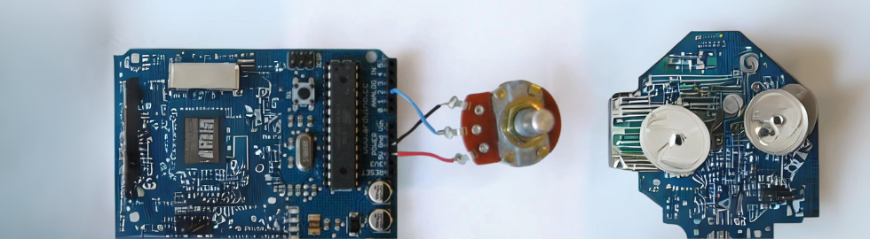
For this we connect three wires to the Arduino board. The first wire goes from one of the outer pins of the potentiometer to ground (GND). The second goes from 5 volts to the other outer pin of the potentiometer. The third wire goes from analog input 2 to the center pin of the potentiometer.

By turning the shaft of the potentiometer, we change the resistance value on either side of the wiper connected to the center pin of the potentiometer. This changes the relative "proximity" of this pin to 5 volts and ground, giving us a different analog input.
When the shaft is turned all the way one way, 0 volts goes to the pin and we read 0. When the shaft is turned all the way the other way, 5 volts goes to the pin and we read 1023. In between, analogRead () returns a number between 0 and 1023 that is proportional to the voltage applied to the pin.
Arduino Code:
/* Analog Read to LED
 * ------------------
 *
 * turns on and off a light emitting diode(LED) connected to digital
 * pin 13. The amount of time the LED will be on and off depends on
 * the value obtained by analogRead(). In the easiest case we connect
 * a potentiometer to analog pin 2.
 *
 * Created 1 December 2005
 * copyleft 2005 DojoDave <http://www.0j0.org>
 * http://arduino.berlios.en
 *
 */
int potPin = 2; // select the input pin for the potentiometer
int ledPin = 13; // select the pin for the LED
int val = 0; // variable to store the value coming from the sensor
void setup() {
 pinMode(ledPin, OUTPUT); // declare the ledPin as an OUTPUT
}
void loop() {
 val = analogRead(potPin); // read the value from the sensor
 digitalWrite(ledPin, HIGH); // turn the ledPin on
 delay(val); // stop the program for some time
 digitalWrite(ledPin, LOW); // turn the ledPin off
 delay(val); // stop the program for some time
}